Difference between revisions of "Case Definitions"
From Alta Dynamics Knowledge Center
(→Vector) |
|||
| Line 5: | Line 5: | ||
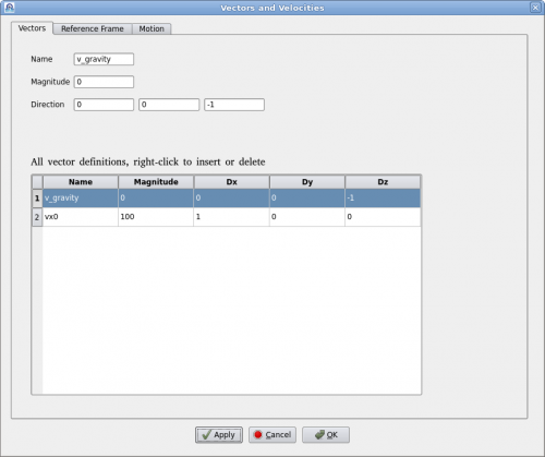
A vector is defined by a name, magnitude and direction in x, y, z. Vector's name must be unique. User can add or delete a vector by right-clicking the table. To edit an existing vector, click on the vector in the table and edit it above. Then click on "Apply" to accept the changes. | A vector is defined by a name, magnitude and direction in x, y, z. Vector's name must be unique. User can add or delete a vector by right-clicking the table. To edit an existing vector, click on the vector in the table and edit it above. Then click on "Apply" to accept the changes. | ||
| + | |||
| + | =Reference Frame= | ||
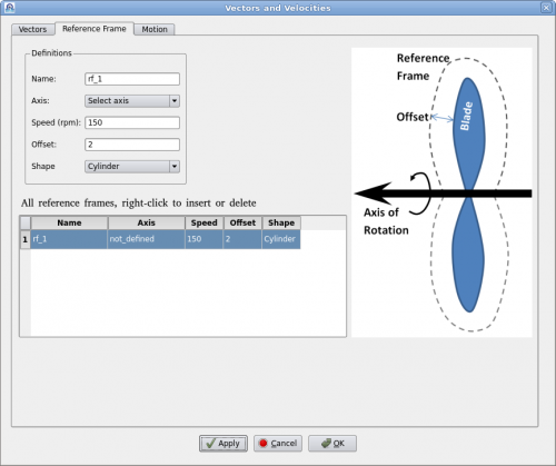
| + | A reference frame is a technique to model continuous rotation with a fixed axis. Users define a reference frame by giving a name, rotational speed (rpm) and axis. Then assign it to a geometry such as a fan or a rotor. | ||
| + | |||
| + | [[File:Setup_rf.png|500px]] | ||
=Movement= | =Movement= | ||
| + | |||
| + | [[File:Setup_movement.png|500px]] | ||
=Global Parameters= | =Global Parameters= | ||
Revision as of 12:22, 24 July 2015
Contents
Vector
Clicking on menu "Setup->Definitions" will bring up the "Vector Definition" dialog as shown below.
A vector is defined by a name, magnitude and direction in x, y, z. Vector's name must be unique. User can add or delete a vector by right-clicking the table. To edit an existing vector, click on the vector in the table and edit it above. Then click on "Apply" to accept the changes.
Reference Frame
A reference frame is a technique to model continuous rotation with a fixed axis. Users define a reference frame by giving a name, rotational speed (rpm) and axis. Then assign it to a geometry such as a fan or a rotor.


