Difference between revisions of "Case Definitions"
(→Boundary Conditions) |
(→Inlet/Outlet) |
||
| (One intermediate revision by the same user not shown) | |||
| Line 77: | Line 77: | ||
=Inlet/Outlet= | =Inlet/Outlet= | ||
| + | |||
| + | Polaris CFD supports a variety of inlet and outlet (IO) definitions. When a user defines an IO, the following steps shall be considered | ||
| + | # Specify the IO type, i.e. pick “Inlet” or “Outlet”. | ||
| + | # Pick a category, candidates are “Static pressure”, “Total pressure”, “Total temperature”, “Fixed velocity”, “Fixed mass flux” and “Floating”. | ||
| + | # Specify the combination of variables accordingly. Depending on the IO type and category, as well as which turbulence model is selected, some variables may not be activated for input. | ||
| + | |||
| + | Note that once FT_FIXED_SOURCE is defined at inlet, FT_FLOATING usually is set at outlet. Otherwise the case might be over specified. | ||
[[File:Setup_io.png|500px]] | [[File:Setup_io.png|500px]] | ||
=Simulation Domain= | =Simulation Domain= | ||
| + | |||
| + | The simulation domain (simd) in Polaris CFD is typically a box with six faces. The box is aligned to the coordinate axes and the computational grid. | ||
[[File:Setup_simd.png|500px]] | [[File:Setup_simd.png|500px]] | ||
| + | |||
| + | Simd faces can be defined as inlet/outlet, wall or symmetry plane. When a face is defined as a wall, a boundary condition can be assigned. A simd face can also be defined as periodical. | ||
[[ Category:Case Setup ]] | [[ Category:Case Setup ]] | ||
Latest revision as of 17:56, 24 July 2015
Polaris CFD adopts SI units in setting up a simulation. All quantities, such as velocity, density and temperature etc are in their corresponding SI unites.
Contents
Vector
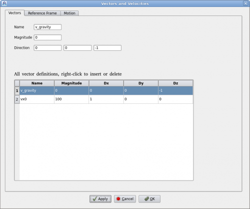
Clicking on menu "Setup->Definitions" will bring up the "Vector Definition" dialog as shown below.
A vector is defined by a name, magnitude and direction in x, y, z. Vector's name must be unique. User can add or delete a vector by right-clicking the table. To edit an existing vector, click on the vector in the table and edit it above. Then click on "Apply" to accept the changes.
Reference Frame
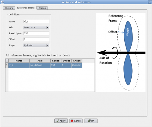
A reference frame is a technique to model continuous rotation against a fixed axis. Users define a reference frame by giving a name, rotational speed (rpm) and axis. Then assign it to a geometry such as a fan or a rotor. Polaris CFD solver will create an internal axisymmetric region to encompass the geometry. The internal geometry will be larger than the volume of swept by the rotational geometry. The "Offset" value dictates how much bigger it will be. The internal geometry can also be "Cylinder" or "Fit" in shape.
A "Fit" shaped reference frame is illustrated in the figure above. An axis of rotation must be defined prior to defining the reference frame. Users can define multiple reference frames by right-clicking the table. It may be noted that when there are other geometries near the rotation geometry, the offset value must be carefully chosen so that the reference frame does not intersect the other geometries.
Motion
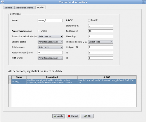
Polaris CFD supports two kinds of motions, prescribed motion and 6-DOF motion. A motion can be either prescribed or 6-DOF, but it cannot be both at the same time. Polaris CFD solver will handle all movements by rediscretization. A continuous rotation against a fixed axis can be defined as a motion as well. Reference frame will not be created.
"Prescribed motion" can have a translation velocity and a time history profile. Such a profile must be defined prior to defining the motion. Same applies for rotations.
"6-DOF motion" is defined by its starting and ending times. Mass and moments of inertia must be defined as well.
After defining a motion users can assign it to appropriate geometries/regions.
Global Parameters
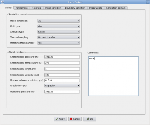
This page contains some of the most important parameters for setting up a simulation. Most of the parameter names are self-explanatory and are common in most CFD software. Users shall make sure all these parameters are correctly selected/entered.
User can choose one of four different analysis types, i.e. direct numerical simulation (DNS) and three turbulence models. When the flow speed is very low, e.g. less than Mach 0.05, users can set "Matching Mach number" to "No". Then input "Max expected velocity" to be 3 or 5 times the characteristic velocity, depending on the actual situation. This will accelerate the simulation significantly.
The "Comment" text box is for users to enter some text for self reference. This text will be printed when the Polaris Solver runs.
Variable Resolution
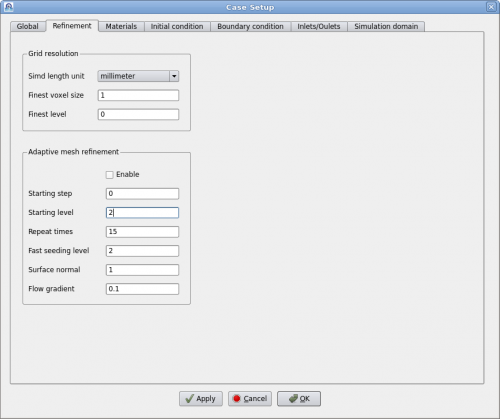
The "Refinement" tab defines the variable resolution (VR) used for simulation. Users define finer grids at interested locations to achieve better accuracy without significant penalty of computational cost.
The first entry is "Simd length unit". Users can choose one of the commonly used units: millimeter, meter, inch, foot, etc. This tells Polaris CFD that all geometries that user imported and created are in this length unit. Users do not need to manually scale each geometry unless several imported geometries are in different units.
The "Finest voxel size" is defined in the chosen length unit as well. The "Finest level" is an integer to define the finest level. Polaris CFD's variable resolution starts at level 0, the coarsest level. Coarsest voxel size = Finest voxel size x 2^(Finest level). For example, if finest voxel size is 0.03mm and the finest level is 5, the coarsest voxel size at level 0 is 0.03 x 2^5 = 0.96 mm.
Adaptive mesh refinement (AMR) is a favorable feature to activate the module in Polaris CFD solver to dynamically refine the simulation grid based on certain criteria. For example users can use AMR to refine the grid along a shock wave after it's formed during simulation.
AMR process itself costs time and slows down the simulation. Users can specify when to start AMR and how often to perform AMR. "Flow gradient" is a parameter to control the sensitivity of AMR regridding. Smaller value will trigger more cells/voxels, i.e. larger regions to be refined.
"Fast seeding level" is a feature to run a simulation with the coarse levels, up to the seeding level first. Finer levels will be added when AMR kicks in. This feature will run simulation fast initially to damp out all the initial effects.
"Surface normal" is a way to control refinement along edges and sharp corners. A smaller value indicates a sharper edge.
Materials
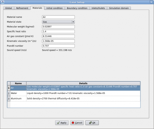
Users can define different materials, such as gas, fluid and solid, for simulation. Each material must have a unique name and a set of properties.
Initial Conditions
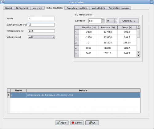
Initial condition is a set of the initial values assigned to a region of fluid or solid. In Polaris v3.60 only fluid regions are assigned with initial conditions. Users can define multiple initial conditions and assign them to different fluids.
It is possible to create an initial condition according to the atmosphere at different elevations. To do that simply enter the elevation and click on "Create IC IO". The corresponding initial condition (pressure and temperature) will be created. User just needs to assign a velocity vector.
Boundary Conditions
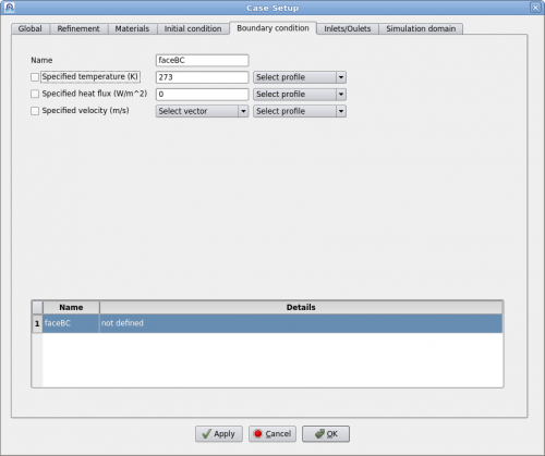
Boundary conditions are assigned to faces (geometry surfaces). Polaris CFD supports three types of boundary conditions, "Specified temperature", "Specified heat flux" and "Specified velocity". "Specified temperature" and "Specified heat flux" are only effective when heat transfer is activated in the "Global" tab. Only one of them can be enabled at a time.
"Specified velocity" means moving wall boundary condition.
Inlet/Outlet
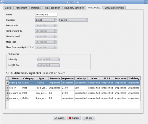
Polaris CFD supports a variety of inlet and outlet (IO) definitions. When a user defines an IO, the following steps shall be considered
- Specify the IO type, i.e. pick “Inlet” or “Outlet”.
- Pick a category, candidates are “Static pressure”, “Total pressure”, “Total temperature”, “Fixed velocity”, “Fixed mass flux” and “Floating”.
- Specify the combination of variables accordingly. Depending on the IO type and category, as well as which turbulence model is selected, some variables may not be activated for input.
Note that once FT_FIXED_SOURCE is defined at inlet, FT_FLOATING usually is set at outlet. Otherwise the case might be over specified.
Simulation Domain
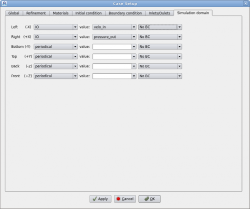
The simulation domain (simd) in Polaris CFD is typically a box with six faces. The box is aligned to the coordinate axes and the computational grid.
Simd faces can be defined as inlet/outlet, wall or symmetry plane. When a face is defined as a wall, a boundary condition can be assigned. A simd face can also be defined as periodical.
