Case Definitions
Contents
Vector
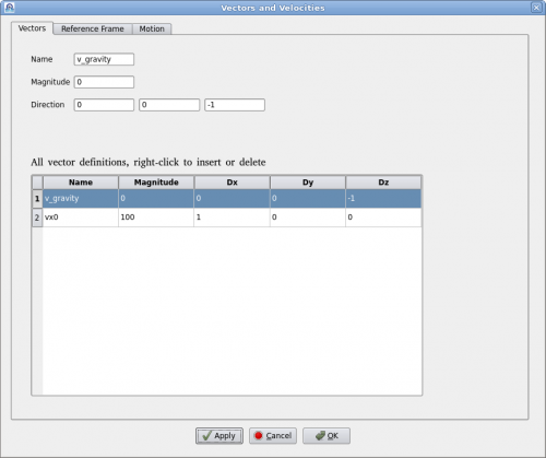
Clicking on menu "Setup->Definitions" will bring up the "Vector Definition" dialog as shown below.
A vector is defined by a name, magnitude and direction in x, y, z. Vector's name must be unique. User can add or delete a vector by right-clicking the table. To edit an existing vector, click on the vector in the table and edit it above. Then click on "Apply" to accept the changes.
Reference Frame
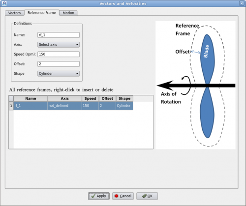
A reference frame is a technique to model continuous rotation against a fixed axis. Users define a reference frame by giving a name, rotational speed (rpm) and axis. Then assign it to a geometry such as a fan or a rotor. Polaris CFD solver will create an internal axisymmetric region to encompass the geometry. The internal geometry will be larger than the volume of swept by the rotational geometry. The "Offset" value dictates how much bigger it will be. The internal geometry can also be "Cylinder" or "Fit" in shape.
A "Fit" shaped reference frame is illustrated in the figure above. An axis of rotation must be defined prior to defining the reference frame. Users can define multiple reference frames by right-clicking the table. It may be noted that when there are other geometries near the rotation geometry, the offset value must be carefully chosen so that the reference frame does not intersect the other geometries.


