Case Definitions
Contents
Vector
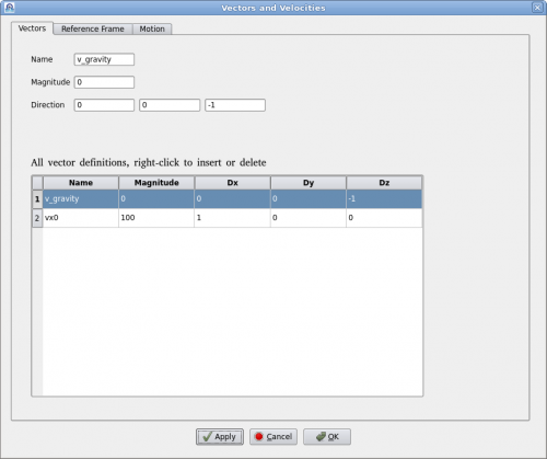
Clicking on menu "Setup->Definitions" will bring up the "Vector Definition" dialog as shown below.
A vector is defined by a name, magnitude and direction in x, y, z. Vector's name must be unique. User can add or delete a vector by right-clicking the table. To edit an existing vector, click on the vector in the table and edit it above. Then click on "Apply" to accept the changes.
Reference Frame
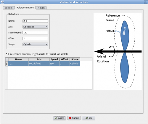
A reference frame is a technique to model continuous rotation against a fixed axis. Users define a reference frame by giving a name, rotational speed (rpm) and axis. Then assign it to a geometry such as a fan or a rotor. Polaris CFD solver will create an internal axisymmetric region to encompass the geometry. The internal geometry will be larger than the volume of swept by the rotational geometry. The "Offset" value dictates how much bigger it will be. The internal geometry can also be "Cylinder" or "Fit" in shape.
A "Fit" shaped reference frame is illustrated in the figure above. An axis of rotation must be defined prior to defining the reference frame. Users can define multiple reference frames by right-clicking the table. It may be noted that when there are other geometries near the rotation geometry, the offset value must be carefully chosen so that the reference frame does not intersect the other geometries.
Motion
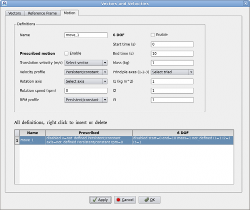
Polaris CFD supports two kinds of motions, prescribed motion and 6-DOF motion. A motion can be either prescribed or 6-DOF, but it cannot be both at the same time. Polaris CFD solver will handle all movements by rediscretization. A continuous rotation against a fixed axis can be defined as a motion as well. Reference frame will not be created.
"Prescribed motion" can have a translation velocity and a time history profile. Such a profile must be defined prior to defining the motion. Same applies for rotations.
"6-DOF motion" is defined by its starting and ending times. Mass and moments of inertia must be defined as well.
After defining a motion users can assign it to appropriate geometries/regions.
Global Parameters
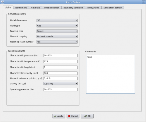
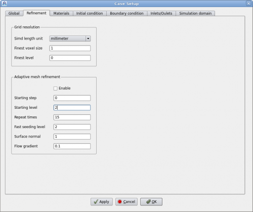
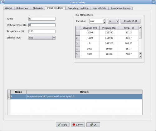
This page contains some of the most important parameters for setting up a simulation. Most of the parameter names are self-explanatory and are common in most CFD software. Users shall make sure all these parameters are correctly selected/entered.
User can choose one of four different analysis types, i.e. direct numerical simulation (DNS) and three turbulence models. When the flow speed is very low, e.g. less than Mach 0.05, users can set "Matching Mach number" to "No". Then input "Max expected velocity" to be 3 or 5 times the characteristic velocity, depending on the actual situation. This will accelerate the simulation significantly.
The "Comment" text box is for users to enter some text for self reference. This text will be printed when the Polaris Solver runs.
