Difference between revisions of "Internal geometries"
(→Triad Axes) |
(→Triad Axes) |
||
| Line 71: | Line 71: | ||
A triad axes is a set of three orthogonal axes. User shall specify the location and X Z axes. The Y axis is computed internally. A triad axes is useful for defining the local reference coordinates for an object. | A triad axes is a set of three orthogonal axes. User shall specify the location and X Z axes. The Y axis is computed internally. A triad axes is useful for defining the local reference coordinates for an object. | ||
| + | |||
| + | All triad axes show X axis in red, Y in yellow and Z in green. No text label is displayed. | ||
[[Category:Geometries]] | [[Category:Geometries]] | ||
Latest revision as of 09:12, 25 July 2015
Polaris CFD can create several kinds of geometries internally. These geometries are relatively simple in shape, but common to many analyses. This feature is very handy for many users.
Click on menu "Setup->Create" to see a list of geometries that can be created.
Contents
Airfoil
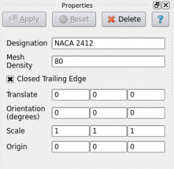
The airfoil created by Polaris CFD is based on NACA 4-digit designation. It is extruded in Z direction by 1. There is no taping. This airfoil is intended for 2D analysis.
User can change the four numerical numbers to create different NACA airfoils. The mesh density refers to the number of segments along the airfoil circumference. A large number would generate a dense mesh. Hit "Apply" to make the changes effective.
The matrix on the bottom half of the "Properties" panel is the transformation matrix. It can be seen for other objects.
Amplitude
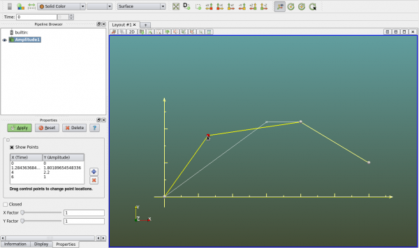
Amplitude is mulit-linear x y relation that is used for specifying time-history of some boundary conditions. It can be created as a geometry object so that users can see the polylines that represent the amplitude. User can set the view to 2D in -Z direction.
The "+" and "-" buttons in the "Properties" panel are for adding and deleting points. User can manually enter the X Y values of each point. User can also drag the little sphere in the view to modify the polyline, as seen in the figure below.
The actual X (time) Y (amplitude) values used by the solver are scaled by the X Y factors respectively.
Always hit "Apply" in the "Properties" panel to save all changes.
Axis
Axis is an object that can be created and placed at specific locations. For example when users want to define a reference frame, the rotational axis must be given. An axis can be created and placed at the center of rotation for this purpose.
An axis is defined by the origin and direction. The third entry "Length" is for display purpose. Unless otherwise stated Polaris CFD solver does not use the length of the axis.
Box
A box is a useful geometry in Polaris CFD. It can be used to represent the simulation domain, a VR domain or a solid object.
A box is defined by X Y Z lengths and its center.
Cone
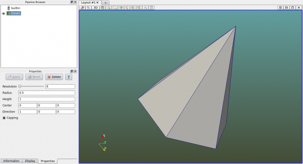
To create a cone, users shall specify its radius, height, center and direction. The resolution refers the number of segments along the circumference. If "Capping" is unchecked the cone's bottom cap will not be created.
Cylinder
Cylinders can be created similar to cones. However cylinders are created in Y direction. User can use the transformation matrix in the "Display" panel to transform the cylinder after it's created.
Line
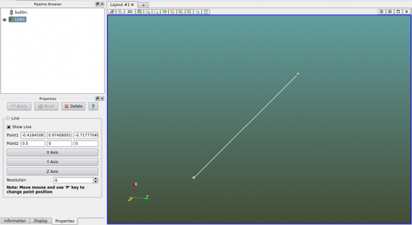
A line is created by specifying two points. User can either manually enter the coordinates or drag the points in the view. To create a line along one of the coordinate axes, simply click on the axis button in the "Properties" panel.
Point
Points can be used as probes to collect data at certain points. They can be used for other purposes as well. To create a point, simply enter three coordinates or drag the point to desired location. For 2D analysis the z coordinate is not used by the solver.
Sphere
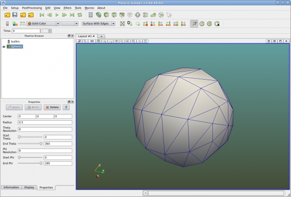
A sphere is defined by the center and radius. User can specify the mesh density by entering "Theta Resolution" and "Phi Resolution". Theta and Phi refer to the spherical coordinates.
User can also specify the range of Theta and Phi if a partial spherical surface is desired.
Text
Text is usually created for display purpose. It is more commonly used in postprocessing.
Triad Axes
A triad axes is a set of three orthogonal axes. User shall specify the location and X Z axes. The Y axis is computed internally. A triad axes is useful for defining the local reference coordinates for an object.
All triad axes show X axis in red, Y in yellow and Z in green. No text label is displayed.
