Internal geometries
Polaris CFD can create several kinds of geometries internally. These geometries are relatively simple in shape, but common to many analyses. This feature is very handy for many users.
Click on menu "Setup->Create" to see a list of geometries that can be created.
Contents
Airfoil
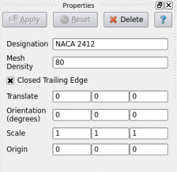
The airfoil created by Polaris CFD is based on NACA 4-digit designation. It is extruded in Z direction by 1. There is no taping. This airfoil is intended for 2D analysis.
User can change the four numerical numbers to create different NACA airfoils. The mesh density refers to the number of segments along the airfoil circumference. A large number would generate a dense mesh. Hit "Apply" to make the changes effective.
The matrix on the bottom half of the "Properties" panel is the transformation matrix. It can be seen for other objects.
Amplitude
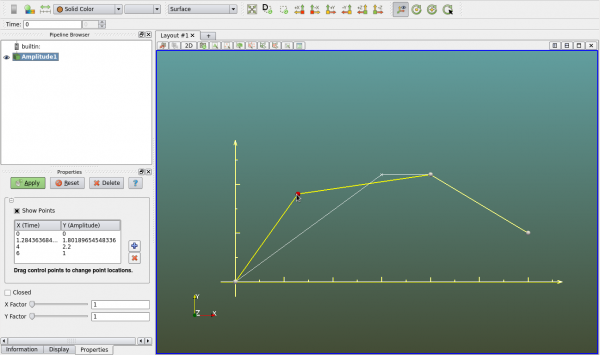
Amplitude is mulit-linear x y relation that is used for specifying time-history of some boundary conditions. It can be created as a geometry object so that users can see the polylines that represent the amplitude. User can set the view to 2D in -Z direction.
The "+" and "-" buttons in the "Properties" panel are for adding and deleting points. User can manually enter the X Y values of each point. User can also drag the little sphere in the view to modify the polyline, as seen in the figure below.
The actual X (time) Y (amplitude) values used by the solver are scaled by the X Y factors respectively.
Always hit "Apply" in the "Properties" panel to save all changes.

